Changes by last author:
Added:
|
A dyno is used for mapping the torque output (on the tires or crankshaft) against loadsites (RPM and MAP and other factors).
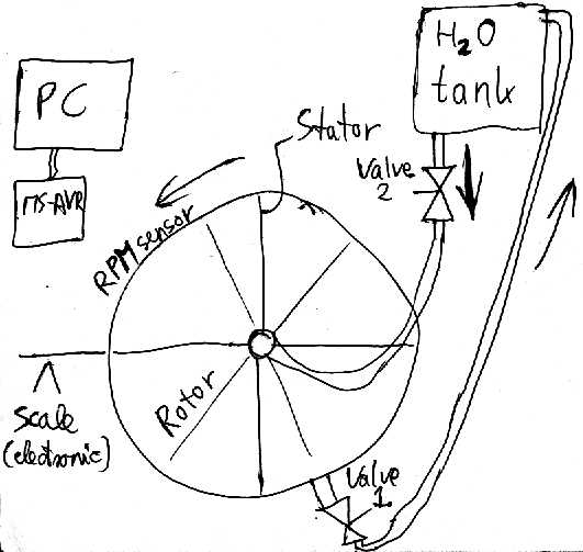
Dynoing can be done in 2 ways: * the car is fixed: chassisdyno (more expensive, but has obvious advantages) * the car is accelerating it's own mass (streetdyno), this requires some smart (but not very hard) data processing to be useful. ---- If you want to build a water-brake dyno, here are some hints. You have to do more research, of course:
* as the wheels rotate a rotor inside the drum, the internal losses will brake. The internal losses will depend to a large degree on the water-level inside the drum (and also on the square of RPM): if it's filled with air, much less braking, than when filled with water. * an electronic scale measures torque (Nm) applied by braking * ball bearings hold the drum in place. Note, that some of the bearings will hold a significant part of the car-weight. * RPM must be measured - unless the car provides his own VSS sensor, which is proportional * electronically controlled valve1 empties the drum (using the centripretal force - smart, isn't it?) to a water-tank * electronically controlled valve2 fills more water into the drum by gravity - into the center of the drum, where centripretal force does not make it hard. * a simple board such as MS-AVR GenBoard collects the data, and controls the water-level (note: you have to write some software, not very hard) * PC logs/displays the data and prints graphs (it can control the valves and read the scale and RPM directly, of course, but that requires more IO and real-time processing on the PC). ---- There are some code in MS-AVR GenBoard (on uC for logging and perl that runs on the PC for processing) to help mapping the ignition advance of a factory ignition and tuning the engine to max performance without a classical dyno: * take a substantially flat (at least not very steep, constant climbing) road (take care!) * Log high precision RPM while accelerating with full throttle in 2nd gear from idle to redline. * Display characteristic extract of the data (the Power=constant*RPM*dRPM/dt) using perl * tuning: change the hiMAP VE or ignition advance somewhat, and see if it got better. Take care! (bad settings of both ignition and VE can cause huge troubles) Here are some logs from MembersPage/MichaelKristensen's car (this is converted from binary to text with a perl oneliner): http://home.caffrey.dk/megasquirt/dump/log1.gz I'm not sure if csv can contain formulas, so in xls form (oops, this is many megabytes, avoid this, use the log1.gz above...): http://www.x-dsl.hu/genboard/dyno/log1.xls ----- here is the comm.c part (see UartComm for more details) that generated the (original binary) log: <code> // convert datastructures to megasquirt compatible format uint8_t MTsendRTvar(uint8_t i) { // uint8_t a, b; switch (i) { case 0: return (uint8_t)rtc.sec; //secl case 2: return engine.status; //engine case 3: return sensors[BARO]; //baro case 4: return sensors[MAP]; //map case 5: return sensors[MAT]; //mat case 6: return sensors[CLT]; //clt case 7: return sensors[TPS]; //tps case 8: return sensors[BATT]; //batt case 9: return sensors[EGO]; //ego case 10: return corr.ego; //egocorr case 11: return corr.air; //aircorr case 12: return corr.warm; //warmcorr case 13: return engine.rpm; //rpm case 14: return mult16_8(inj_port1.pwcalc, 41)>>10; //pw case 15: return corr.tpsaccel; //tpsaccel case 16: return corr.baro; //barocorr case 17: return corr.gammae; //gammae case 18: return corr.ve; //vecurr ifdef MT_IACPOS case 19: return iac.position; endif ifdef MT_IGNADVANCE case 20: return engine.current_ignadv; endif ifdef MT_RPM case 21 : if (debug.auto_log) pushfunc(&MTsendRTvar, 22); return (engine.rpm_64 & 63) << 2; endif default: return 0; // blank spot 1,2,3 } }</code> ---- The ugliness comes from the traditional megatune-protocol compatibility: the fine precision rpm is available: RPM = 100*( v13 + v21 / 256); See comm.c (above) for the slight differences relative to the traditional 22byte megatune 'A' output. It contains precision RPM (a must for dyno-ing) and also the measured ignition advance (measured with GenBoard INT6 input relative to the missing tooth index signal of the 36-2 trigger on IC3 input). If someone feels like playing with it, extract the * ignition map (v20 in the structure) * torque curve (without exact scaling, since the mass, gear-ratio and tire-size unpublished) Publish programs or formulas used (perl or octave (==matlab) preferred, but others also good) Partial results also welcome. What can you expect? If you collect data per loadsites (RPM/MAP values), you will find 4 or 5 angular acceleration (dRPM/dt) layers. These are according to the gear ratios. At 4th gear you will find much lower acceleration at the same (MAP,RPM) loadsite than in 1st gear. If you have a VSS (vehicle speed sensor) data logged, this is simpler. Even than, there will be some noise (layers not very narrow) because of hill-climbing and downhilling. This can be corrected if you log GPS data at the same time (GPS modules are available <90 Euro). Even with flat-areas or GPS-elevation-correction you will have finite-width layers because of changing wind-vector. This can be decreased with averaging. To know the output of the engine, besides the acceleration force F1 = a * m = dv/dt * m = dRPM/dt * const/gearslowing * m you need to add another force: F2=friction force which can be measured by logging fuelcut deacceleration. You deaccelerate over the useful RPM-range in all gear-ratios. In this fuelcut mode, MAP does not count, only RPM and gear. You will use the same F2 for any MAP. From this F2 you can find out the CW air-drag coefficient of your car: you need to find the 2nd order coefficient in the F=a*v*v + b*v + c formula (hint: simulated annealing of above a,b,c coefficients and v-initial variable targetting the minimal square of error of diff between measured and calculated deceleration curves - I got some perl code - Marcell). Unfortunately I do not know Mik's gear ratios, tiresize and weight. See also GenBoard/TuneAndDrive and MembersPage/RedMist/SoftwareDyno [opensource street-dyno software and some theory] A non-opensource software to evaluate data: http://www.tweecer.com/StreetDyno/index.html There is a chassisdyno yahoo group. ---- See also * http://www.land-and-sea.com/dyno-tech-talk/cell_design.htm |