Subpage of Motorsport menu
Table Of Contents
Cam control outline
Cam control measurement prerequisites
Cam control configuration
Cam control actuation explained per control type
Cam control position measurement and configuration notes per trigger type
Cam control hardware changes in case of retrofit
VEMS camshaft control, allows you to fully closed loop control (with independent PID regulation and targets for each cam) the camshaft angle on intake and exhaust camshafts (brand specific cam control abbreviations: VVTI/AVCS/VANOS); In the default configuration 2 controllable channels are available, when selecting 4 cam control (available since 1.2.34 firmware), wheelspeed is sacrificed in favor of cam control, allowing the maximum of 4 controllable channels.
2 camshaft control operation:
- 2 Channels
- Secondary trigger (when enabled) measures position of intake cam and is regulated according to target from camshaft intake target table
- Third trigger (when enabled) measures position of exhaust cam and is regulated according to target from camshaft exhaust target table
4 camshaft control operation:
- 4 Channels
- Secondary trigger (when enabled) measures position of intake 1 cam and is regulated according to target from camshaft intake target table
- Third trigger (when enabled) measures position of exhaust 1 cam and is regulated according to target from camshaft exhaust target table
- Wheel speed 1/Fourth trigger measures position of intake 2 cam and is regulated according to target from camshaft intake target table
- Wheel speed 2/Fifth trigger measures position of exhaust 2 cam and is regulated according to target from camshaft exhaust target table
Cam control measurement prerequisites
- Secondary trigger, maximum of one measurement pulse allowed per cam rotation after secondary filtering is applied
- Third/Fourth and Fifth trigger, can have multiple pulses per cam rotation as long as they are equally spaced; make sure to adjust your trigger edge accordingly
- Usable triggers:
- missing tooth type, camsync: coil-type and third trigger:coil-type
- OR (BMW dual VANOS) Primary trigger: missing tooth type camsync: extrapulse-type and third trigger: coil-type (last pulse measured)
- OR (BMW quad VANOS) Primary trigger: missing tooth type camsync: extrapulse-type and third/fourth/fifth trigger: coil-type (last pulse measured)
- OR Primary trigger: coil-type camsync: coil-type and third trigger: coil-type
- OR (Honda) Primary trigger: extrapulse-type camsync: extrapulse-type and third trigger: coil-type (last pulse measured)
- OR Primary trigger: Subaru 36-2-2-2 camsync: Subaru special and third trigger: Subaru special
- OR Primary trigger: Suzuki 36-2-2-2 camsync: Suzuki special and third trigger: Suzuki special
- Any other trigger combination is unsupported.
In general, the "measure tooth" should be configured, so the sectrig (and third trig) position measures 5-35 degrees normally (that means appr 40-75 when fully advanced. For example 100 degrees is too high, just lower "measure tooth", and the target table should be lowered accordingly to match the measured values, of course) For more information regarding position measurement, see: Cam control position measurement and configuration notes per trigger type
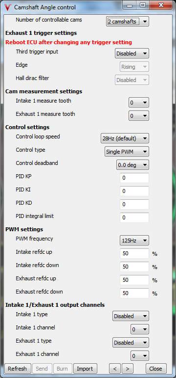
Number of controllable cams
- 2 cams (default): 2 controllable camshaft axis
- 4 cams (BMW Quad VANOS): 4 controllable camshaft axis but sacrificed wheelspeed inputs in favor of cam control axes
Realtime data set (4 cam control)
- Int 1 and Exh 1: Intake 1 and Exhaust 1 cam measured values and actuated dutycycles are reported in realtime data
- Int 2 and Exh 2: Intake 2 and Exhaust 2 cam measured values and actuated dutycycles are reported in realtime data
Third trigger input/Edge
Enable when using the third trigger for cam control, when unconnected set to disable, adjust trigger edge so it confirms with rules from prerequisites.
Third trigger Hall Dirac filtering
Filter small diract pulses which do not contain information
Intake/Exhaust 1/2 measure tooth
Adjust to conform with general setup notes (on cam target when full advanced) above
Intake 1/2 and Exhaust 1/2 phase correction (4 cam control)
Adjust so the measurement offset between the Intake 1/2 (and Exhaust 1/2) becomes zero
Control loop speed
Update frequency of the PID control loops (for all axis) when in doubt use default 28Hz
Control type for control actuation details, see: Cam control actuation explained per control type
- Single PMW: One control solenoid per camshaft axis
- Dual (Vanos): Dual control solenoids per camshaft axis (advance/retard control)
Control deadband
Deadband around target, inside the deadband solenoid actuation is in hold position (mid PWM or VANOS both solenoids active)
PID KP/KI/KD/Integral limit
PID controller behavior tuning parameters
PWM frequency
PWM actuation frequency, when in doubt use 100-125Hz
Intake/Exhaust refDc up
Reference dutycycle where the cam position starts to move slowly up
Intake/Exhaust refDc down
Reference dutycycle where the cam position starts to move slowly down
Intake/Exhaust output type/channels
Select the output channels where the cam solenoids are connected
Cam control actuation explained per control type
- The PID parameters, PWM period and Output type are common to exhaust and intake camshaft control.
- The PWM period: 25Hz to 375Hz
- The output channel and reference position can be set separately to each camshaft control (for single PWM only)
- For exhaust control the third trigger input must enable and reboot ECU to enable position measurement.
- The target can be set in the target tables (located in the menu under this dialog).
- Single PMW control:
- Use injector or ignition output if solenoid resistance is ( smaller than 4ohm -> 3A current)
- Control method:
- Under 450 RPM: Output inactive
- Measured = 0 ... target - control_deadband deg: RefDc down + PID action applied (Cam pulse too early)
- Measured = (target - control_deadband deg) .... (target + control_deadband deg): (RefDc up + down) / 2 = Mid Ref Ductycycle applied
- Measured = (target + control_deadband deg) ... 360 deg: RefDc Up + PID action applied (Cam pulse too early)
- Dual Vanos Output type (typically BMW):
- Two outputs used per actuated channel one advance, one retard solenoid.
- PFET controlled, PFET outputs normally driven by p259 outputs (check your ecu's documentation for specifics)
- Control method:
- Under 450 RPM : OutputA (Advance) and OutputB (Retard) inactive
- Measured = 0 ... target - control_deadband deg - PWM-ing range : OutputA active and OutputB inactive , Cam pulse too late
- Measured = (target - control_deadband deg - PWM-ing range) ... (target - control_deadband deg) : OutputA active and OutputB PWM-ing (closer to target = PWM duty higher)
- Measured = (target - control_deadband deg) .... (target + control_deadband deg): OutputA and OutputB both active
- Measured = (target + control_deadband deg) .... (target + control_deadband deg + PWM-ing range): OutputA PWM-ing and OutputB active
- Measured = (target + control_deadband deg + PWM-ing range) ... 360 deg: OutputA inactive and OutputB active (Cam pulse too early)
Cam control position measurement and configuration notes per trigger type
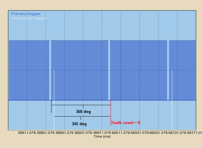
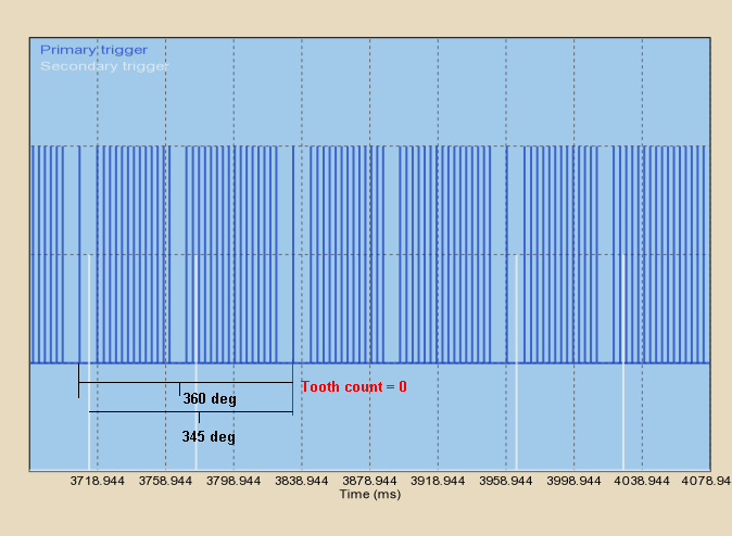
- Missing tooth type:
- the Camshaft tooth measured to the Tooth count configured in the "Measuring at tooth_cnt" (first tooth (tooth_cnt = 0) is the first after the missing tooth)
- for example cam angle = 345 degree, measuring at tooth_cnt = 0:
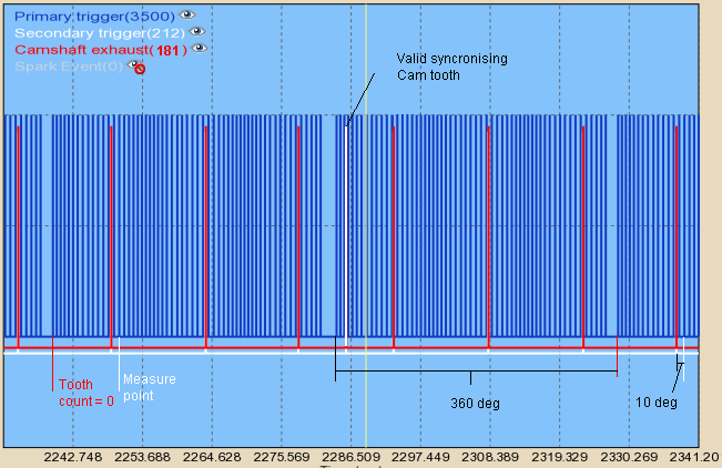
- Missing tooth type with extrapulse cam (BMW dual Vanos):
- the last camshaft tooth measured before the Tooth count configured in the "Measuring at tooth_cnt". (Tooth_cnt = 0 is the tooth right after missing tooth).
- the 6+1 extra pulse (exhaust-cam) trigger must be connected to secondary trigger, the evenly-spaced 6 pulse (intake-cam) connected to third trigger input (so the "exhaust target" table is actually for the intake)
- for example cam angle = 10 degree, measuring at tooth_cnt = 14 (this is just an example, measure tooth is usually lower, see above):
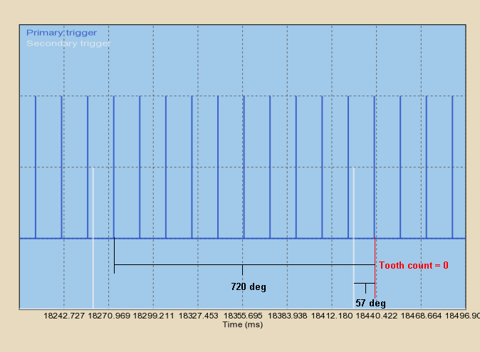
- Coil type:
- the Camshaft tooth measured to the Tooth count configured in the "Measuring at tooth_cnt", next primary tooth is Tooth count = 0,
- so maximum angle difference can be measured is tooth width
- for example cam angle = 345 degree(but it is bigger than 72 deg so 345 modulo 72 = 57), measuring at tooth_cnt = 0:
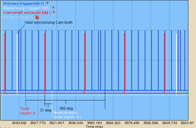
- Coil type with extrapulse cam (Honda):
- the Camshaft tooth measured to the Tooth chosen by "Measuring at tooth_cnt" variable. Tooth count = 0 is the primary pulse after the primary extrapulse after the valid sectrig sync pulse. With the actual triggerlog (different than this example-shot), good values are apparently measuring at tooth_cnt = 4,10,16 or 22 but rather 5,11,17 or 23.
- the 4+1 extra pulse trigger must be connected to secondary; the evenly placed 4 pulses to third trigger input
- Example: exhaust cam angle = 31 degree, cam angle=156 degree, measuring at tooth_cnt = 4:
- Subaru 36-2-2-2 under fw 1.1.92:
- the first Camshaft tooth (after the long gap) measured to the Tooth count = 0
- for example cam angle = 345 degree:
- Subaru 36-2-2-2 above fw 1.1.92:
- Suzuki 36-2-2-2 above fw 1.1.92:
Cam control hardware changes in case of retrofit
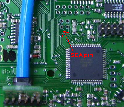
- On ecu's which came without third trigger option from the factory (confirm using your ecu spec sheet), the third trigger is a processor input pin without any protection .
- To retrofit third trigger input on these ecu's, use Pull-up resistor, a 10k protection resistor, and protection Diode, and a 22nF capacitor (min 10nF) between processor pin and GND.
Historic information: Firmware 1.1.81 uses a (slightly) different algorithm the details here
.