Subpage of Base setup menu
Table Of Contents
Direct PWM ETC Control
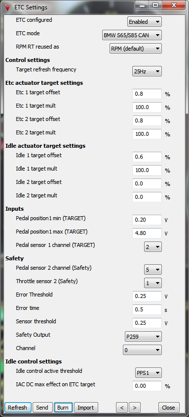
BMW S65/S85 CAN ETC Control
VEMS v3 ECU Electronic Throttle (ETC) Overview
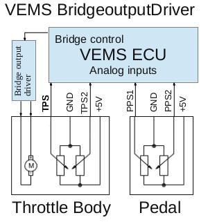
Wiring:
The motor of your throttle is always connected through a safety shutoff relay, this output is enabled when all sensor readings makes sense.
The electronic throttle has 2 position sensors, one is wired to the ECU's TPS input, one is wired to a spare analog input, and configured as TPS2.
The pedal also has 2 sensors, which are both wired to spare analog inputs, and named PPS1 and PPS2. Some pedals are using internal HALL sensors (lowside only feedback),
these pedals require a 2k7 pullup to 5v on both PPS1/PPS2 analog channels on v3 side.
In the case one of the 2 sensors has a higher resolution, this goes to the TPS and PPS1 for better control resolution.
HW Setup:
- Disable injector PWM-ing. ETC control with BridgeOutputDriver and injector PWM-ing are mutually exclusive, meaning you can use either but not both at the same time; When Low-Z injectors are present fit series resistors
(4.7Ohm power resistors, one for each injector) after disabling PWM-ing in Injector Settings
- Select your safety relay channel
- Choose channel numbers for PPS1, PPS2 and TPS2
Calibration:
- Start with your safety relay detached, so no power goes through to the throttle motor.
- Enter your high and low voltage of your PPS1 input
- Open the ETC Gauge group (View -> gauge groups -> ETC)
- Calibrate the PPS2 curve by slowly depressing the pedal and fill in the PPS2 voltage in each cell
- Fill your "ETC reference curve" with 50% to start with if you cannot find a good example setting for your throttle. This will be set later by watching your throttle duty cycle and input for each cell, most important for throttles with limp home mode.
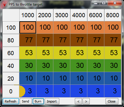
- Make sure your PPS to throttle target table is set, a somewhat progressive curve is recommended.
- If it is possible, use your hands to move the throttle to repeat the calibration process for TPS2 curve. If that isn't possible, the safety relay has to be bypassed for this calibration by changing "sensor threshold" to a very high value, and use pedal to calibrate this.
Do NOT drive the car with the safety function bypassed, or before the throttle is perfectly tuned.
- Firmware upgrade must always be done under an expert's supervision (via local, or remote assistance), and new settings must be set properly / verifed carefully.
This is especially important for an install with electronic throttle.
Please do NOT use "borrowed" config or request such.
Follow all the calibration and verification steps.
Defaults for the PID controller as included on the dialog picture below is a good starting point, watch the throttle and/or the throttle target/throttle position diff gauge and adjust the pid settings accordingly.
There is a separate PPS to target table for ALS.
Idle control can be set up with an external valve and / or the electronic throttle in any combination, to use the ETC for idle control, calibrate the
"Idle control max ETC position" accordingly, the value set here is what the ETC target will be with commanded IAC duty = 100%.
So use IAC (idle) controller even if you don't have a dedicated IAC valve, this variable will command actuation.
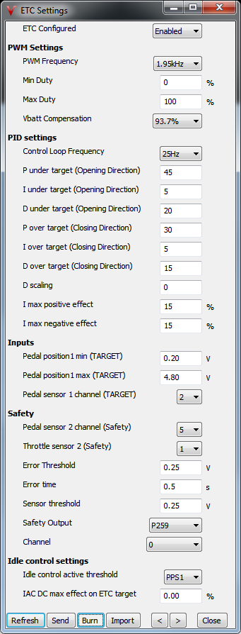
New settings since 1.2.31-1.2.32 firmware:
- I max positive/negative effect (duty%): Positive/negative absolute duty limits on total integral effect. Start conservative, if all other settings have been optimized they can be increased to increase the controller stiffness around target.
- D scaling: Scaledown factor for D term effect when setpoint changes, prevents against D term "derivative kick". When in doubt, disable (0).
- Vbatt Compensation: Percentage of theoretical Vbatt compensation applied against difference from center dutycycle (50%) in direction of change. Suggested default 94%.
IAC tricks in the ETC PPS=>TPS table is a bad idea.
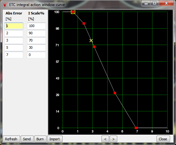
ETC integral action window curve:
When on target and getting a sudden target step up (or down), the I staying active could actually dim the control reaction.
This is where the integral scaling curve can help.
Obviously, in the example, integral contribution (to actuator PWM action) is 0 when seriously off-target, so in that case control depends on P term and reference position:
Reasonably reference positions and PID P term needed.
A useful example as a lesson (how to make ETC tuning extremely difficult and frustrating: this actually happened)
- Chosing a LARGE ETC valve (for the engine)
- Not using a dedicated IAC valve
- Using large injectors (relative to cyl displacement), with shitty response
- Not reading ETC Help text, and as a result:
- Instead of using IAC control and IAC DC "max effect", trying to set ETC PPS => throttle target table (with 5 bins from 500..1500 RPM, and 1 bin at 7000 RPM) so that engine behaves even if AC or coolant fan suddenly turns on.
(this strategy is often used by less sophisticated controllers, but it's very limited and should not be used except as a last resort)
- Not asking for professional support
(by firing vemslog and a few sentences about the situation)
They managed to tune (proper injectors were needed for perfect result), but it took several days (and quite a bit of frustration, most likely).
Would have been easier by some study and summarizing the situation (+ vemslog) so it's possible for experts to help.
VEMS v3 ECU BMW S65/S85 CAN ETC Control
DISCLAIMER: The S65/S85 engine is a very complicated engine, the wiring and setup of CAN ETC/Idle control should only be attempted by VERY experienced installers, removing the stock management will break (or limit) functionality of the stock car (everything except the engine might no longer work).
Requirements:
- Vems V3 ecu ordered with special CAN upgrade
- Vems V3 firmware version 1.2.34 (or higher)
- BMW S65/S85 engine
Wiring:
| BMW S65/S85 ETC/Idle actuator connections to V3 controller |
| Function |
V3 Pin |
ETC actuator side pin |
ETC ecu side pin |
ETC wire color |
Idle actuator side pin |
Idle ecu side pin |
Idle wire color |
Notes |
| CAN High |
breakout CAN_H |
X5392/6 |
X60005/20 |
Yellow/Black |
X6939/2 |
X60005/21 |
Yellow/Black |
ETC #2 connector X5393, Idle #2 connector X6938 |
| CAN Low |
breakout CAN_L |
X5392/5 |
X60005/42 |
Yellow/Brown |
X6939/1 |
X60005/43 |
Yellow/Brown |
ETC #2 connector X5393, Idle #2 connector X6938 |
| Safety Output |
P259/X |
X5392/1 |
X60005/17 |
Blue/Yellow |
|
|
|
ETC #2 connector X5393/1, ecu side X60005/39 (Blue/Green) |
| TPS |
EC36/1 |
X62521/3 |
X60005/37 |
Violet/White |
|
|
|
ETC #2 TPS2 connect to v3 analog in, connector X62522/3, ecu side X60005/36 (Violet/Black) |
| 5v Supply |
breakout 5v |
X62521/6 |
X60005/14 |
Red/Violet |
|
|
|
ETC #2 connector X62522/6, ecu side same as ETC #1 |
| GND |
EC36/26 |
X62521/5 |
X60005/38 |
Brown/Violet |
|
|
|
ETC #2 connector X62522/5, ecu side same as ETC #1 |
The CAN controlled ETC actuators are using a common safety output channel (P259/X) to control their enable lines (X5392/1 and X5393/1), this output is enabled when all sensor readings make sense.
Connect the CAN bus lines of your v3 to the CAN_H and CAN_L of the ETC actuators (see table for pin numbers) and join this CAN bus with the CAN bus of the Idle actuators CAN_H and CAN_L, termination of 240ohm is inside the ecu for s65, s85 has no ecu side termination resistor.
The S65/S85 electronic throttle system has 2 position sensors (one per bank), one is wired to the ECU's TPS input the other one (other bank) is wired to a spare analog input and configured as TPS2.
The pedal also has 2 sensors, which are both wired to spare analog inputs, and named PPS1 and PPS2, do not forget to wire up PPS sensor supply and GND. Some pedals are using internal HALL sensors (lowside only feedback),
these pedals require a 2k7 pullup to 5v on both PPS1/PPS2 analog channels on v3 side.
In the case one of the 2 sensors has a higher resolution, this goes to the TPS and PPS1 for better control resolution.
HW Setup:
Select your safety relay channel, important control will be disabled without this channel filled.
Choose channel numbers for PPS1, PPS2 and TPS2
Calibration:
- Start with your safety output (going to ETC enable lines) detached, so throttle motor driver is disabled.
- Select ETC mode: "BMW S65/S85 CAN" and power cycle your ecu.
- Fill all ETC/Idle target offsets and mults with zero (0.0).
- Calibrate your TPS signal (manually moving the throttle of the bank in question) min (closed) to max (full open).
- Calibrate the TPS2 calibration curve, (manually moving throttle of other bank) fill min (closed) voltage at TPS 1% 0, fill max (full open) voltage at TPS 1% 100 (last cell) interpolate in between.
- Enter your min and max voltage of your PPS1 input (pedal up to fully pressed pedal).
- Calibrate the PPS2 curve by slowly depressing the pedal and fill in the PPS2 voltage in each cell.
- Select RPM RT reused as "CAN ETC #1 Pos", your RPM gauge will now show the selected variable; Calibrate the ETC#1 target offset (closed), fill with RPM value/10; Next move throttle to full position manually
and fill ETC #1 target mult with (RPM/10) - offset (normally around 100.0%).
- If your RPM gauge shows 65535 for all selected position variables make sure your actuators are wired correctly and powered; This value indicates an communication problem between ecu and actuators.
- If your RPM gauge shows 2047 for one (or more) of the selected position variables this indicates an error with the actuator itself, check wiring from position sensor to actuator.
- If your RPM gauge shows 0 for all of the selected position variables this indicates an error in the communication between CAN module and v3 mainboard, e.g. module not present.
- Same procedure for but select RPM RT reused as "CAN ETC #2 Pos"; Calibrate the ETC #2 target offset and ETC #2 target mult.
- Select RPM RT reused as "CAN IDLE #1 Pos"; Calibrate the IDLE #1 target offset (0.5-0.8%) and IDLE #1 target mult (100.0%).
- Same procedure for second IDLE valve but select RPM RT reused as "CAN IDLE #2 Pos"; Calibrate the IDLE #2 target offset (0.5-0.8%) and IDLE #2 target mult (100.0%).
- Disable Idle DC Max effect on target (0.0%) when using the stock idle valve(s).
- Make sure your PPS to throttle target table is set, a somewhat progressive curve is recommended.
- Select RPM RT reused as "RPM" after calibration.
- Reconnect your safety output (going to ETC enable lines), throttle motor driver is now enabled.
Example default settings: